




CSBP-1
Still deciding? Please contact us immediately!
Current product category
CSBP-1
Still deciding? Please contact us immediately!
Current product category
Key words
- Product Description
-
CORONA S.BUS Programming
Card CSBP-1 Manual
Thank you for purchasing CORONA's S.BUS programming card CSBP-1. CSBP-1 is a collection of S.BUS servo programming, S.BUS decoder programming and up to eight-cell Li-Po battery pack voltage measurement function handheld triple-function device.
Port description:

There are three modes in S.BUS programming card.
LED1 displays "A" that indicate programming function of S.BUS servo.
LED1 displays" b "that indicate programming function of S.BUS decoder.
LED1 displays "C" that indicate voltage measuring of li-Po batterys.
When you need to measure the battery voltage you should not have the power port (4.8~6.0V)poweron, and do not plug in the device to be programmed to avoid damage. After power left or right click SW2to select modes from“A”,"b” and“C”.
Mode ”A”:
1.Power on programming card. Let S.BUS servo connect to the programming interface. When thedigitalLED1 displays "A", press the middle button of SW2, enter mode "A". When the right three digital LEDdisplay"-","-"-" indicates servo has'been linked. If not displayed, press the center button of SW2 againto link servos.
2. After a successful link, left or right click of SW2 to select servo's parameters.
LED1 display 1: Servo Reverse parameter is set to "0" indicates reverse turn, "1" indicates a positiveturn.Left or right key click to switch through SW1. Servo writing by pushing the middle button of SW1.
LED1 display 2: Servo Channel number set(1~18:chl~ch16,DG1 and DG2), Left or right key click toswitch through SW1.Servo writing by pushing the middle button of SW1.
LED1 display 3: Servo Right Travel Adjust(50%~175%),left or right key click to decrease or increase.Servo writing by pushing the middle button of SW1.
LED1 display 4: Servo Left Travel Adjust(50%~175%),left or rightkey click to decrease or increase.Servo writing by pushing the middle button of SW1.
·LED1 display 5: Servo Neutral Offset(-30deg~+30deg),left or right key click to decrease or increase.Servo writing by pushing the middle button of SW1.
· LED1 display 6: Servo travel range testing. SW1 Left key click indicate the smallest servo valueoutput. SW1 right key click indicate the largest servo value output. If want the middle servo value output,switch to other item except 6,and turn back.
3.When you push down SW1 to write parameters, the I FD1-LED4 will flash 1 or 2 seconds,if the flashtime is longer than normal operation, please write the parameters again.
4.After write operation, you should repower on the programming card and link the servo to check allparameters you have wrote.
Mode ”b”:
1.Power on the programming card, connect the S.BUS decoder to the programming interface, switch to“b”by left or right key click of SW2. Push down the middle button of SW2 to link the decoder. IfLED2~LED4 display “-”,”-”,”-" indicate a successful link. If have no display, please link decoder again.
2.After a successful link, left or right key click of SW2 to change the physical port item.
Port"1”: LED2~LED4 display the servo channel number of port 1. All number of servochannel(1~18:CH1~CH16,DG1 and DG2) can be programmed. Left or right key click of SW1 to changethe servo channel number. Servo writing by pushing the middle button of SW1.
Port”2”: LED2~LED4 display the servo channel number of port 2. All number of servochannel(1~18:CH1~CH16,DG1 and DG2) can be programmed. Left or right key click of SW1 to changethe servo channel number. Servo writing by pushing the middle button of SW1.
·Port"3": LED2~LED4 display the servo channel number of port 3. All number of servochannel(1~18:CH1~CH16,DG1 and DG2) can be programmed. Left or right key click of SW1 to changethe servo channel number. Servo writing by pushing themiddle button of SW1.
3.After write operation, you should repower on the programming card and link the decoder to checkall parameters you have wrote.
Mode'" C " :
1.Connect the Li-Po battery to the battery test port of the programming card at right pin order.
"G"indicate the negative electrode of the lowest cell.Left or right key click of SW2 to select mode “C",push down the middle button of SW2 and enter battery voltage test mode.
2.LEDI display the cell number of the battery package,LED2~LED4 indicate the voltage value of thecurrent cell.
3,"t"indicate the total voltage of the batery package.
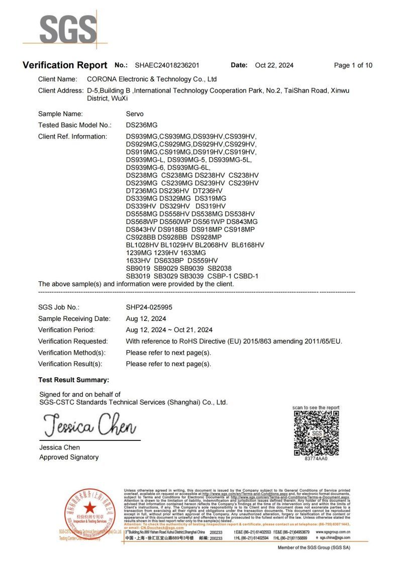
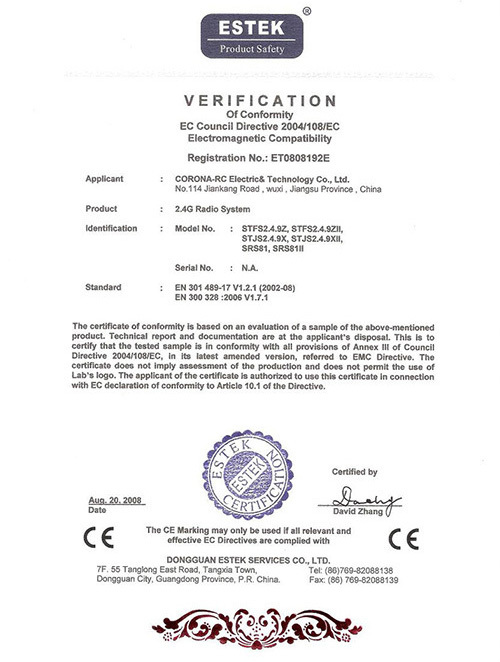
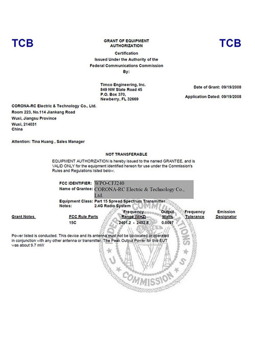
Certificates









Inquire Now
Note: Please leave your email address, our professionals will contact you as soon as possible!
Address:
D-5,Building B ,International Technology Cooperation Park, No.2, TaiShan Road, Xinwu District, WuXi
Tel:
E-mail:
Quick Navigation
Online Message
If you have any product related questions, please feel free to contact us!
Copyright © 2024 CORONA ELECTRONIC AND TECHNOLOGY CO.,LTD.丨 Business License